← Back to Projects
Matt Haywood
3D Renderer
I decided to program a 3D renderer from scratch using Pygame and Numpy (numerical python) libraries. I decided to use Python as it is good prototyping and for learning the basics of matrices and matrix transformations. I aim to transfer this project to OpenGL in C++ in the future.
Transformation Matrices
The most important part of the 3D renderer is the transformation matrices. These transformation matrices include rotation matrices in the x,y and z axis. The matrices are multiplied with the vertices, edges and faces of a model to rotate them by a certain angle. The matrices project the 3D object to a 2D surface by rotating the vertices by different amounts in the X and Y axis depending on the Z coordinate.
X Axis Rotation
\[xAxis = \begin{bmatrix} 1 & 0 & 0 & 0\\ 0 & cos\theta & -sin\theta & 0\\ 0 & sin\theta & cos\theta & 0 \\ 0 & 0 & 0 & 1 \end{bmatrix}\]
Y Axis Rotation
\[yAxis = \begin{bmatrix} cos\theta & 0 & sin\theta & 0\\ 0 & 1 & 0 & 0\\ -sin\theta & 0 & cos\theta & 0 \\ 0 & 0 & 0 & 1 \end{bmatrix}\]
Z Axis Rotation
\[zAxis = \begin{bmatrix} cos\theta & -sin\theta & 0 & 0\\ sin\theta & cos\theta & 0 & 0\\ 0 & 0 & 1 & 0 \\ 0 & 0 & 0 & 1 \end{bmatrix}\]
There are a number of other transformation matrices such as translation, scale and perspective matrices that are also important to give depth to the 3D renderer.
The rotation matrices on their own rotate the model around the origin, meaning that they will rotate the shapes around the sides of the screen. The image below shows this with the pygame screen in the bottom right of the axis. This shows how the model is rotated around \(x = 0\) and \(y = 0\). An offset is needed to correct this so that the rotation is around the center of the screen.
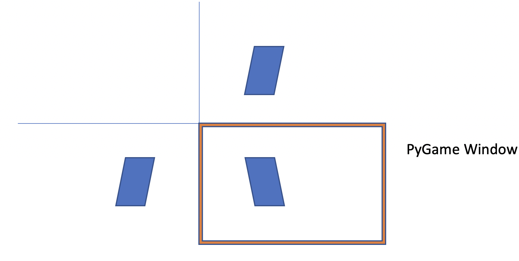
A translation matrix is used to translate the center of the screen to the top left. The rotation is performed and the screen is translated back to the center.
Translation Matrix
\[translation(dx,dy,dz) = \begin{bmatrix} 1 & 0 & 0 & 0\\ 0 & 1 & 0 & 0\\ 0 & 0 & 1 & 0 \\ dx & dy & dz & 1 \end{bmatrix}\]
    def rotate_about_Center(self, Axis, theta):

		#First translate Centre of screen to 0,0

		wf = Wireframe()
		matrix = wf.translationMatrix(-self.width/2,-self.height/2,0)

		for wireframe in self.wireframes.values():
			wireframe.transform(matrix)

		#Do Rotation
		wf = Wireframe()
		if Axis == 'X':
			matrix = wf.rotateXMatrix(theta)
		elif Axis == 'Y':
			matrix = wf.rotateYMatrix(theta)
		elif Axis == 'Z':
			matrix = wf.rotateZMatrix(theta)

		for wireframe in self.wireframes.values():
			wireframe.transform(matrix)

		#Translate back to centre of screen
		wf = Wireframe()
		matrix = wf.translationMatrix(self.width/2,self.height/2,0)

		for wireframe in self.wireframes.values():
			wireframe.transform(matrix)
Scale Transformations
A scale transformation is used to increase or reduce the size of the 3D shape.
View Matrix / Adding Perspective Matrix
Perspective is the fact that when objects are further away, they look smaller. This means in terms of matrix transformations, we need a transformation matrix that scales X and Y coordinates down based on their Z coordinate, as Z is the depth. The larger the Z coordinate, the smaller the object needs to be.
    def transform_for_perspective(self, center, fov, zoom):
		self.perspective_nodes = self.nodes.copy()
		for i in range(len(self.nodes)):
			node = self.nodes[i]
			p_node = self.perspective_nodes[i]
			if node[2] != 0:
				p_node[0] = center[0] + (node[0]-center[0])*fov/(zoom-(node[2]))
				p_node[1] = center[1] + (node[1]-center[1])*fov/(zoom-(node[2]))
				p_node[2] = node[2] * 1
The code above is used to add perspective to the 3D points of rendered objects, making further away points move towards the center of the screen depending on their z coordinates. The persepective is rendered on every loop of the display function making sure that the perspective is calculated after any rotations.
Camera and Game controls
A Camera class is used to change the viewing angle and to move throughout the model. To move the camera, the awsd keys are used to translate everything relatively to the camera using a translate all function.
The Key event listeners wait for a key to be pressed and then execute the corresponding functions to move the camera about the model.
    while running:

			keys = pygame.key.get_pressed()

			for event in pygame.event.get():
				if event.type == pygame.QUIT:
					running = False

			if keys[pygame.K_LEFT]:
				key_to_function[pygame.K_LEFT](self)
			if keys[pygame.K_RIGHT]:
				key_to_function[pygame.K_RIGHT](self)
			if keys[pygame.K_DOWN]:
				key_to_function[pygame.K_DOWN](self)
			if keys[pygame.K_UP]:
				key_to_function[pygame.K_UP](self)
			if keys[pygame.K_u]:
				key_to_function[pygame.K_u](self)
			if keys[pygame.K_h]:
				key_to_function[pygame.K_h](self)
			if keys[pygame.K_k]:
				key_to_function[pygame.K_k](self)
Rendering Distances and Clipping boxes
To make sure that only the vertices, edges and faces that are infront of the camera are rendered, a clipping box is needed to get rid of any of the vertices that go outside the cameras renderering view. This is done to improve the performance of the program. A rendering distance is also added so that past a certain distance the objects are not rendered.
Below is a simple function that takes a vertex from a model and checks whether it is within the screens height, width and infront of the camera. It also checks that it is not greater than a depth of 50000.
    def clipNode(self, node):

		x = self.width
		y = self.height
		z = 50000
		clippedNode = 0

		if node[0] > x or node[0] < 0:
			return 0

		if node[1] > y or node[0] < 0:
			return 0

		if node[2] < z and node[2] > 0:
			clippedNode = node
		else:
			return 0

		return clippedNode
Shown below is a video of the clipping box being used. The nodes at the edge of the screen are removed. This is working however needs improvement. It can be seen that as a node is removed, the edge connecting to the node is also removed. A method is needed to continue the line to the edge of the screen even after the node has been removed.
Adding Faces
Faces are used to show that an object is a solid and can also be shaded to give an illusion that there are lights lighting up various parts of a model.
PyGame has a very useful function 'drawPolygon()'. This function can be used to draw a multiple sided 2D shape. This program uses this function to draw many triangle shapes by supplying the function with three vertices from the wireframe vertex list. A class was also implemented called 'Face'. This class holds the vertex index information and also the material index of the face.
A small peice of code was also added to the display() function to iterate through the wireframes faces and draw the faces that make up the wireframe.
    if self.displayFaces and wireframe.showFaces:
		for face in wireframe.faces:
			n1, n2, n3 = face.vertices
			clipN1 = self.clipNode(wireframe.perspective_nodes[n1])
			clipN2 = self.clipNode(wireframe.perspective_nodes[n2])
			clipN3 = self.clipNode(wireframe.perspective_nodes[n3])

			if type(clipN1) == int or type(clipN2) == int or type(clipN3) == int:
				pass
			else:
				cull = self.backFaceCull(clipN1, clipN2, clipN3)
				if cull:
					pass
				else:
					pygame.draw.polygon(self.screen, [self.processLighting(face) * x for x in face.material], [clipN1[:2], clipN2[:2], clipN3[:2]], 0)
	else:
		pass
A very simple face sorting function was added in order to do Z buffering. Z Buffering is used to makesure that certain faces occlude others depending on their depth.
The face sorting functions are shown below:
    def sortFaces(self):
		self.faces.sort(key=self.sortKey, reverse=True)

    def sortKey(self, inputs):
	    return (self.perspective_nodes[inputs[0]][2] + self.perspective_nodes[inputs[1]][2] + self.perspective_nodes[inputs[2]][2])/ 3.0
OBJ Loader
To load in pre-made models, an OBJ Loader class was implemented. This class is used to parse in a OBJ file and separate into vertices, edges and faces.
In an OBJ File 'v' is vertex and 'f' is face and 'vn' is vertex normal used for shading. An array is setup to add the vertices which can then be referenced by the faces.
    def process_file(self):

		f = open(self.filename, "r")

		if len(self.materialDictionary.keys()) == 0:
			self.materialDictionary['default'] = (255,0,0)

		material = ''

		for i in f:

			if i[0] == 'v' and i[1] == 't':
				pass

			elif i[0] == 'v' and i[1] == 'n':
				i = i.split()
				self.vertexNormalArray.append([(float(i[1])*self.scaleFactor), (float(i[2])*self.scaleFactor), (float(i[3])*self.scaleFactor)])

			elif i[0] == 'v' and i[1] == ' ':
				i = i.split()
				self.nodeArray.append([(float(i[1])*self.scaleFactor), (float(i[2])*self.scaleFactor), (float(i[3])*self.scaleFactor)])

			elif i.find('usemtl') != -1:
				i = i.split(' ')
				material = i[1]

			elif i[0] == 'f':

				i = i.split()
				face = []
				faceVertexNormals = []
				for subsection in i:
					subsections = subsection.split('/')
					if subsections[0] != 'f':
						face.append(subsections[0])
						faceVertexNormals.append(subsections[2])
				if len(face) == 4:
						#Create two triangles
					triangle1 = Face((int(face[0])-1, int(face[1])-1, int(face[2])-1), self.getFaceNormal(self.vertexNormalArray[int(faceVertexNormals[0])-1], self.vertexNormalArray[int(faceVertexNormals[1])-1], self.vertexNormalArray[int(faceVertexNormals[2])-1]), self.materialDictionary[material])
					triangle2 = Face((int(face[2])-1, int(face[3])-1, int(face[0])-1), self.getFaceNormal(self.vertexNormalArray[int(faceVertexNormals[2])-1], self.vertexNormalArray[int(faceVertexNormals[3])-1], self.vertexNormalArray[int(faceVertexNormals[0])-1]), self.materialDictionary[material])

					self.edgeArray.append((int(face[0])-1, int(face[1])-1))
					self.edgeArray.append((int(face[1])-1, int(face[2])-1))
					self.edgeArray.append((int(face[2])-1, int(face[0])-1))
					self.edgeArray.append((int(face[2])-1, int(face[3])-1))
					self.edgeArray.append((int(face[3])-1, int(face[0])-1))
					self.edgeArray.append((int(face[0])-1, int(face[2])-1))
					self.faceArray.append(triangle1)
					self.faceArray.append(triangle2)
				elif len(face) == 3:
						#Create one triangle
					triangle1 = Face((int(face[0])-1, int(face[1])-1, int(face[2])-1), self.getFaceNormal(self.vertexNormalArray[int(faceVertexNormals[0])-1], self.vertexNormalArray[int(faceVertexNormals[1])-1], self.vertexNormalArray[int(faceVertexNormals[2])-1]), self.materialDictionary[material])
					self.edgeArray.append((int(face[0])-1, int(face[1])-1))
					self.edgeArray.append((int(face[1])-1, int(face[2])-1))
					self.edgeArray.append((int(face[2])-1, int(face[0])-1))
					self.faceArray.append(triangle1)

				else:
					pass

			elif i[0] == 'm':
				#use material to add the colour to the face
				pass
			else:
				pass

		f.close()
Material File
A OBJ file has an associated .mtl (material) file that contains all the information about the materials used to make up the model. This file contains colours, textures and uv maps for the materials in the model.
At this point, only the colour is used so only the Material Name and 'Kd' is parsed from the file. 'Kd' is diffuse colour which makes up most of the colour in a model. The material name is parsed into a dictionary of materials and the Kd is stored as an rgb colour.
    def process_material_file(self):
		#open the same filename with the .mtl file extension
		filename = self.filename.rsplit(".", 1)
		filename = filename[0] + ".mtl"

		materialName = ''

		f = open(filename, 'r')

		for i in f:
			if i.find('newmtl') == 0:
				i = i.split(' ')
				materialName = i[-1]

			if i[0] == 'K' and i[1] == 'd':
				i = i.split(' ')
				r = float(i[1])*255
				g = float(i[2])*255
				b = float(i[3])*255

				self.materialDictionary[materialName] = (r,g,b)
Backface Culling
Backface culling is used to makesure that any face facing away from the camera is not rendered. This means that when viewing a cube, the oppisite sides will not be rendered, as they will not be seen by the camera. This is done as it improves the performance of the program without changing any of the functionality.
A triangle that is facing towards the camera has a positive area, however, a triangle facing away from the camera has a negative area. If the triangle can be determined whether it is has a positive or negative area, all of the triangles with negative areas can be 'culled'.
The area of the triangle is worked out using the shoelace algorithm. This algorithm is shown below.
\[A = 1/2({x_1}{y_1}-{x_2}{y_1}+{x_2}{y_3}-{x_3}{y_2}+...+{x_n}{y_1}-{x_1}{y_n})\]
Because only the sign is required, the 1/2 can be omitted. This in code looks like:
def backFaceCull(self, n1, n2, n3):

    answer = ((n1[0] * n2[1]) + (n2[0]* n3[1]) + (n3[0] * n1[1])) - ((n3[0] * n2[1]) + (n2[0] * n1[1]) + (n1[0] * n3[1]))

    if answer > 0:
        return True
    else:
        return False
When the face is to be rendered, this function will return either a positive or negative value and this is used to either render or not.
    cull = self.backFaceCull(clipN1, clipN2, clipN3)
    if cull:
        pass
    else:
        pygame.draw.polygon(self.screen, [self.processLighting(face) * x for x in face.material], [clipN1[:2], clipN2[:2], clipN3[:2]], 0)
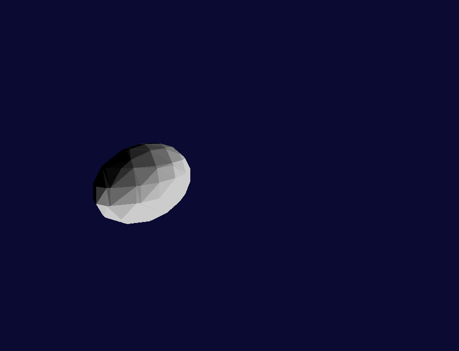
Shading and Lighting
To provide basic shading, a 'Light' class is used. This class holds information about the position, intensity, direction and colour of the light.
Basic shading was added to each of the faces that make up the 3D model. This shading works on the principle that faces facing away from a light appear darker and faces that are pointing directly at a light appear lighter. This means that the shading can be calculated with cos(direction of light - face normal).
The direction of the light and the face normal is calculated using the following calculations.
\[averagedVertexNormal = \begin{bmatrix} (vertexNormalX1 + vertexNormalX2 + vertexNormalX3)/3.0 \\ (vertexNormalY1 + vertexNormalY2 + vertexNormalY3)/3.0 \\ (vertexNormalZ1 + vertexNormalZ2 + vertexNormalZ3)/3.0 \end{bmatrix} \]
\[FaceNormal = \begin{bmatrix} averagedVertexNormal_1 \\ averagedVertexNormal_2 \\ averagedVertexNormal_3 \end{bmatrix} \]
This face normal now needs to be normalised. This is done using the following.
\[FaceNormal = \begin{bmatrix} averagedVertexNormalX / \sqrt{averagedVertexNormalX^2 + averagedVertexNormalY^2 + averagedVertexNormal^2} \\ averagedVertexNormalY / \sqrt{averagedVertexNormalX^2 + averagedVertexNormalY^2 + averagedVertexNormal^2} \\ averagedVertexNormalZ / \sqrt{averagedVertexNormalX^2 + averagedVertexNormalY^2 + averagedVertexNormal^2} \end{bmatrix} \]
If the light source is a omni-directional, the direction vector is calculated as shown below. However if the light is directional, the direction vector will already be given.
The light direction vector will be the difference of the light position and the face normal calculated previously.
\[LightVector = \begin{bmatrix} LightPositionX - FaceNormal_1 \\ LightPositionY - FaceNormal_2 \\ LightPositionZ - FaceNormal_3 \end{bmatrix} \]
This light vector is then normalised to a unit vector using the same method as above.
This is then turned into cos\(\theta\) by calculating the dot product between the light vector and the face normal for each face. This cos\(\theta\) value is clamped between 0 and 1 so that it can't go to -1. This is because light behind a face would not change the shading of the front of a face, the face would stay the same shading as the light angle moves from 90 to 180 degrees behind the face. This value is then multiplied by the material colour for each of the RGB values.
Shading can also be done using vertex normals for 'Smooth Shading', however this is more advanced.
CAD features
To make this piece of software more useful, it was decided to add a user menu and some extra features to create and edit models. These features were a toolbar to access the tools and open existing models, rectangle draw tool, circle draw tool and an extrude tool.
Rectangle Draw Tool
The rectangle draw tool takes two screen clicks and converts them into world coordinates where \(y=0\). The conversion works out from the 2D screen coordinates a set of 3D world coordinates. It is important to note that the screen coordinates are referred to as perspective coordinates. This is because everything that is observed on the screen has been transformed into the perspective matrix. The mouse clicks are clicking in the perspective matrix. in order to find where these are in the 3D world these clicks have to be inversely transformed.
The screen clicks are converted into world coordinates by solving the following equation for z where \(world_y=0\).
\(Perspective_y = center_y + (world_y-center_y)*\dfrac{fov}{zoom-world_z}\)
Perspective y is the y coordinate of the mouse click on the screen and the \(world_y\) is the world y coordinate which in this case needs to be 0. This can be changed depending on what level the plane is that you want the clicks positions to be.
Rearranged, this gives us:
\(world_z = \dfrac{-(center_y*fov) - (zoom*perspective_y)+(center_y*zoom)}{-y+center_y}\)
Once world z has been worked out, this can be used to find world x position of the click.
\(world_x = \dfrac{(perspective_x*(zoom-world_z))-(center_x*(zoom-z))}{fov+center_x}\)
These are then used as a 3D point \(\begin{bmatrix} world_x & 0 & world_z\end{bmatrix}\)
Once this is done for two points, the other two points of the rectangle can be generated and turned into a rectangle. The two faces of the rectangle are also added.